
International Power Products Market
Sourcing and supply chain management for overseas buyers and Chinese manufacturers.
View specificationsTransformers deployed across transmission, distribution, railway traction, and international power markets. Configurations match voltage class, cooling method, and compliance standards. Sourced via integrated quality management systems.
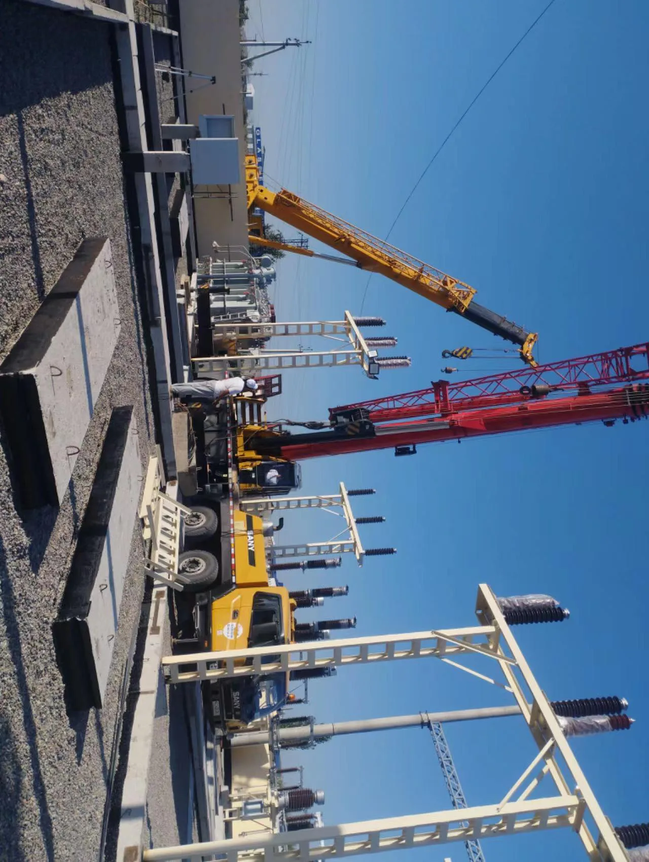
Deployed across transmission, distribution, railway, and international power markets.
Sourcing and supply chain management for overseas buyers and Chinese manufacturers.
View specificationsDesigns adapted to site constraints: climate, noise, topology.
Powerbridge acts as an agency between specification writers and manufacturing partners. Local constraints are translated into engineering parameters: ambient climate, audible noise limits, short-circuit withstand, fault levels, and network topology. Each unit is configured for its exact duty by the manufacturer.
Power Transformers, Grid Transformers, Auto-Transformers, Step Up/Down Transformers, Railway Transformers, Three Phase Pad Mounted Transformers, Oil Immersed Transformers, Isolation Transformers, Pole Mounted Transformers, Dry Type Transformers
Powerbridge
Tropical-humid, coastal-salt, and high-altitude environments dictate insulation class, creepage distance, anti-condensation heaters, and coating systems. Specifications are defined per site altitude and temperature band.
Urban substations and residential feeders impose strict dB(A) limits. Core design, winding clamping, tank stiffening, and fan selection are tuned by manufacturers to meet required sound levels at the boundary.
Radial, looped, or meshed networks alter fault current, grounding method, and tap range. Impedance, vector group, and protection interface are aligned with existing schemes.
| Parameter | Typical Range | Basis of Selection |
|---|---|---|
| Altitude / Ambient | 0–4000 m · −25 °C to +55 °C | Derating of dielectric strength and cooling margin |
| Insulation Class | ONAN / ONAF / OFAF / ODAF | Load factor and redundancy requirement |
| Audible Noise | 60–85 dB(A) | Distance to nearest receptor and local ordinance |
| Vector Group | Yyn0 · Dyn11 · YNd11 · Yzn11 | Grounding method and phase-shift need |
| Tap Changer | OLTC ±9×1.78% · DEHT ±2×2.5% | Voltage regulation across load cycle |
| Short-Circuit Withstand | Up to 4 s rated duration | Fault level and protection clearing time |
Substation data sheet, single-line diagram, and noise or altitude constraints are submitted.
Constraints are mapped to core, winding, cooling, and accessory choices with the manufacturer's design office.
Type-test reports, IEC/ANSI cross-references, and FAT plans are issued before production starts.
Factory accepts the build; inspection, packing, and export logistics are coordinated under agreed Incoterms.
Trusted extension of clients and manufacturing partners in global power trade
Send Specification